Back Cable apantallat Catalan Stíněný kabel Czech Cable apantallado Spanish Kable pantailatu EU کابل حفاظدار FA परिरक्षित केबल HI シールドケーブル Japanese Cabo blindado Portuguese
This article needs additional citations for verification. (November 2008) |


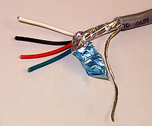
A shielded cable or screened cable is an electrical cable that has a common conductive layer around its conductors for electromagnetic shielding.[1] This shield is usually covered by an outermost layer of the cable. Common types of cable shielding can most broadly be categorized as foil type (often utilizing a metallised film), contraspiralling wire strands (braided or unbraided) or both.[2] A longitudinal wire may be necessary with dielectric spiral foils to short out each turn.[1]
The shield acts as a Faraday cage – a surface that reflects electromagnetic radiation. This reduces both the interference from outside noise onto the signals and the signals from radiating out and potentially disturbing other devices (see electromagnetic compatibility). To be effective against electric fields (see also capacitive coupling), the shield must be grounded.[3] The shield should be electrically continuous to maximize effectiveness, including any cable splices. For high frequency signals (above a few megahertz), this extends to connectors and enclosures, also circumferentially: The cable shielding needs to be circumferentially connected to the enclosure, if any, through the connector or cable gland.[1][4][5]
Some types of shielded cable use the shield as the return path for the signal. As contrasting examples, coaxial cable does, whereas twinax cable does not.
High voltage power cables with solid insulation are shielded to protect the cable insulation, people and equipment.
- ^ a b c "EMC techniques in electronic design Part 2 - Cables and Connectors" (PDF). May 2009. Retrieved 2022-04-18.
For good shielding performance, the electrical bonding between a cable's shield and the shields of its connectors or glands and any shielded enclosures should have no gaps in it either. This means that there should be a seamless low-impedance electrical connection all around the perimeter or circumference of the electrical joint. This is often referred to as 360° shield bonding (even when the connector or gland isn't circular), and it applies between a cable shield and connector shield, the shields of two mating connectors and between the shield of a connector and the metal chassis or structure it is mounted on.
- ^ "Popular Shielding Types". 2021. Retrieved 2022-04-18.
- ^ "Shield Grounding". Retrieved 2019-02-28.
- ^ "Introduction to electromagnetic compatibility" (PDF). Analog Devices. May 2009. Retrieved 2022-04-18.
In summary, for protection against low-frequency (<1 MHz) electric-field interference, grounding the shield at one end is acceptable. For high-frequency interference (>1 MHz), the preferred method is grounding the shield at both ends, using 360° circumferential bonds between the shield and the connector, and maintaining metal-to-metal continuity between the connectors and the enclosure.
- ^ "Effectiveness of Shield Termination Techniques Tested with TEM Cell and Bulk Current Injection" (PDF). NASA. 2009. Retrieved 2022-04-18.
Although it has long been known that pigtail shield connections underperform 360° termination methods, our experiments indicated that pigtails were typically worse by more than 35 dB for frequencies above a few MHz.